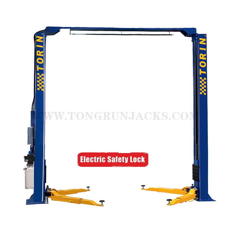
4 Ton 2 Post Overhead Clearfloor
• Fully automatic electric control panel.
• Driven by dual hydraulic cylinders.
• Chain type lifting system.
• Internal Electric locking mechanism, w/two point safety latches in each column.
• Automatic safety arm locks.
• Easy to operate up and down switches on electrical control box.
• Steel wire rope equalizing cables.
• Multi-voltage power supply is available for electrical requirements.
• Optional motors available.
• Adjustable lift pads and adapters
• Durable powder coat finish.
• No Floorplate restrictions.
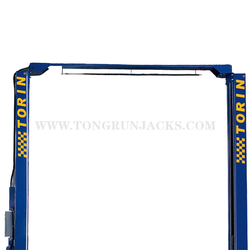
• Overhead crossover beam.
Product Information

Product Parameters
|
Model |
QJY240D-E |
Capacity |
4 Ton |
|
Moter Performance |
2.2 kw |
Electrical Connection |
380V / 220V |
|
Lifting Time |
50 sec. |
Package Size 1# |
3650x470x720 mm |
|
Package Size 2# |
800x280x320 mm |
Package Size 2# |
590x240x250 |
|
N.W. / G.W. |
685 / 700 kgs |
QTY/20'CY |
15 PCS |
Features ELECTRIC SAFETY LOCK
• Fully automatic electric control panel.
• Driven by dual hydraulic cylinders.
• Chain type lifting system.
• Internal Electric locking mechanism, w/two point safety latches in each column.
• Automatic safety arm locks.
• Easy to operate up and down switches on electrical control box.
• Steel wire rope equalizing cables.
• Multi-voltage power supply is available for electrical requirements.
• Optional motors available.
• Adjustable lift pads and adapters
• Durable powder coat finish.
• No Floorplate restrictions.
• Overhead crossover beam.


Sequence of Lockout Procedure
1) Notify all affected employees that a lockout is being performed for servicing or maintenance and that the lift must be shut down and locked out to perform the servicing or maintenance
2) Unload the subject lift (remove vehicle). Shut it down and assure the disconnect switch is "OFF" if one is provided on the lift.
3) The authorized lockout person operates the main energy isolation device removing power to the lift being taken out of service. Stored or residual energy (such as capacitors, springs, elevated machine members, hydraulic systems, air, or etc.) must be dissipated or restrained by methods such as grounding, repositioning, blocking, bleeding down, etc.
If this is a lockable device, the authorized lockout person places the assigned padlock on the device to prevent its unintentional reactivation. An appropriate tag is applied stating the person's name, at least 3" x 6" in size, an easily noticeably color, and states not to operate device or remove tag. If this device is a non-lockable circuit breaker or fuse, replace circuit with a "dummy" device and tag it appropriately as mentioned above.
4) Ensure that the equipment is disconnected from the energy sources' by first checking that no personnel are exposed, then verify the isolation of the equipment by operating the push button or other normal operating controls' or by testing to make certain the equipment will not operate. . Be sure to return any switches to the "OFF" position.
5) The equipment is now locked out and ready for the required maintenance or service.
Restoring Equipment to Service
1) Check the lift and the immediate area around the lift to ensure that nonessential items have been removed (clear all tools, vehicles and personnel) and that the completion of all lift components are operationally intact.
2) The authorized person can now remove the lock (or dummy circuit breaker or fuse) and tag. Activate the energy isolating device so that the lift may again be placed into operation.
- TOP


